This week I used the Adafruit 1.14" 240x135 Color TFT Breakout LCD Display included in our kits and combined it with the microphone to make a congratulatory device that reacts when someone is clapping!
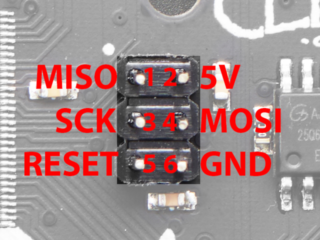
In order to connect the TFT Display to the Metro M0 Express, I first started following this tutorial. I soon realized that I needed to use the 6 SPI pins on the microcontroller in order to wire the TFT Display (credit to Samantha Jones for the following instructions!):
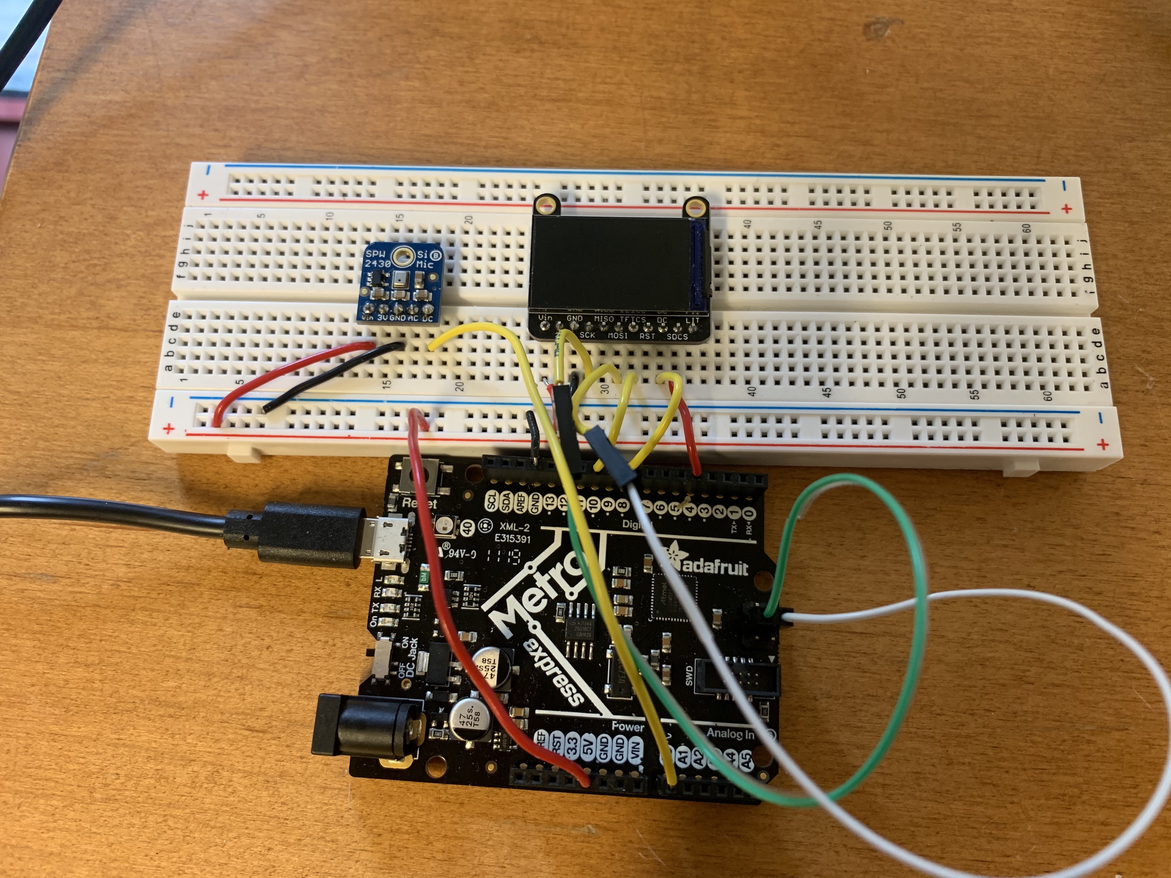
See last week’s assignment for more details about the microphone. This week I connected GND to GND, Vin to 5V, and the DC pin on the microphone to pin A0 on the Metro M0 Express board.
Check out my final circuit:
After programming all of my devices, I followed this tutorial on installing the libraries necessary to run the TFT.
Now I had to combine my microphone code from last week with some sample code from the TFT like this (courtesy of Andrew Zhang):
After playing around with the code for a while and debugging some connectivity issues with my Arduino (pressing the reset button twice might be helpful if you have similar issues!), I was able to run this code to successfully build my congratulatory display:
                #include Adafruit_GFX.h    // Core graphics library
                #include Adafruit_ST7735.h // Hardware-specific library for ST7735
                #include Adafruit_ST7789.h // Hardware-specific library for ST7789
                #include SPI.h
                #if defined(ARDUINO_FEATHER_ESP32) // Feather Huzzah32
                    #define TFT_CS         14
                    #define TFT_RST        15
                    #define TFT_DC         32
                #elif defined(ESP8266)
                    #define TFT_CS         4
                    #define TFT_RST        16
                    #define TFT_DC         5
                #else
                    // For the breakout board, you can use any 2 or 3 pins.
                    // These pins will also work for the 1.8" TFT shield.
                    #define TFT_CS        10
                    #define TFT_RST        9 // Or set to -1 and connect to Arduino RESET pin
                    #define TFT_DC         8
                #endif

                // For 1.14", 1.3", 1.54", and 2.0" TFT with ST7789:
                Adafruit_ST7789 tft = Adafruit_ST7789(TFT_CS, TFT_DC, TFT_RST);

                const int sampleWindow = 500; // Sample window width in mS (50 mS = 20Hz)
                unsigned int sample;

                void setup() {
                    Serial.begin(9600);
                    Serial.print(F("Hello! ST77xx TFT Test"));
                    tft.init(135, 240);           // Init ST7789 240x135
                    Serial.println(F("Initialized"));
                    tft.fillScreen(ST77XX_BLACK);
                    tft.setRotation(3);
                }

                void loop() {

                    unsigned long startMillis = millis();  // Start of sample window
                    unsigned int peakToPeak = 0;   // peak-to-peak level

                    unsigned int signalMax = 0;
                    unsigned int signalMin = 1024;

                    // collect data for 50 mS
                    while (millis() - startMillis < sampleWindow) {
                        sample = analogRead(0);   //reading DC pin from pin A1
                        if (sample < 1024) { // toss out spurious readings
                          if (sample > signalMax) {
                            signalMax = sample;  // save just the max levels
                          } else if (sample < signalMin) {
                            signalMin = sample;  // save just the min levels
                          }
                        }
                    }
                    peakToPeak = signalMax - signalMin;  // max - min = peak-peak amplitude

                    Serial.println(peakToPeak);

                    if (peakToPeak <= 50) {
                        tft.fillScreen(ST77XX_WHITE);
                    } else if (peakToPeak > 15) {
                        tft.fillScreen(ST77XX_BLACK);
                        testfillcircles(10, ST77XX_BLUE);
                        testdrawtext("Yay!", ST77XX_MAGENTA);
                      }
                }

                void testfillcircles(uint8_t radius, uint16_t color) {
                    for (int16_t x=radius; x < tft.width(); x+=radius*2) {
                        for (int16_t y=radius; y < tft.height(); y+=radius*2) {
                          tft.fillCircle(x, y, radius, color);
                        }
                    }
                }

                void testdrawtext(char *text, uint16_t color) {
                      tft.setCursor(0, 0);
                      tft.setTextColor(color);
                      tft.setTextSize(6);
                      tft.setTextWrap(true);
                      tft.print(text);
                }
I played around with the sample window by using the Serial Monitor in the Arduino IDE to track the rate of my clapping and found 500 mS to be a good sample time.
Within the void setup(), I forgot to initialize the TFT
at first using tft.init(135, 240) and found that this resulted in the board
not setting up properly when I ran the code. Additionally, I made sure to use
tft.setRotation(3) because I wanted the display in landscape mode and not
portrait mode (the TFT uses parameters 0, 1, 2, and 3 for rotations,
where 0 and 2 are different portrait modes and 1 and 3 are both different landscape modes.
I used the same code from the microphone from last week to calculate the peak to peak amplitude, and used the peak to peak amplitude to determine if I would change the display or not. I also played around with what value would change the display and tested values ranging from 50 to 100. The chosen value will vary on the environment, and I found that one day the baseline values for the microphone in a silent setting were around 10 while another day they were closer to 30. In this case, when the peak to peak amplitude is less than or equal to 50, the screen is white. Otherwise, the screen fills up with blue circles and “Yay!” is printed in magenta.
I had fun playing with the TFT Display Board, and I hope to do a lot more fun things with it in the future! For now, here’s what I came up with: